
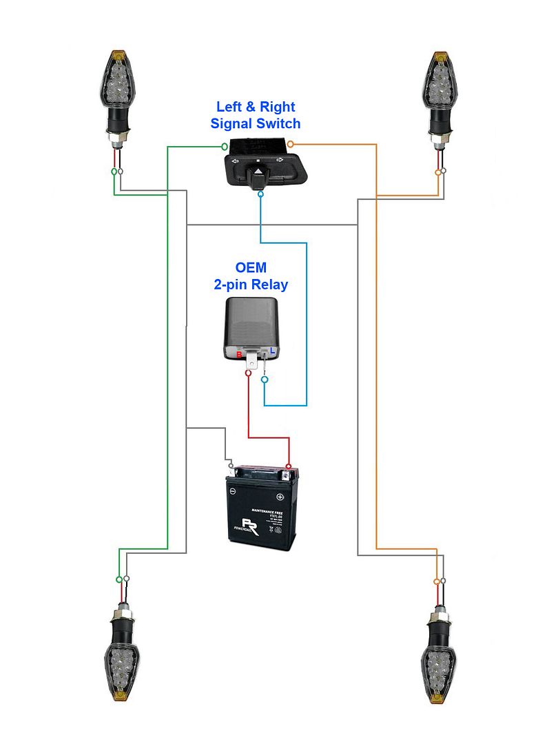
Buell Motorcycle Turn Signal Wiring Diagram
- Category : Wiring Diagram
- Post Date : January 27, 2026
Buell Motorcycle Turn Signal Wiring Diagram
Flush Mount Markers
Motorcycle Oem Or Led Indicators 4

Skene Design Motorcycle Visibility Lights

Suzuki Gsx

Suzuki U2013 Page 5 U2013 Circuit Wiring Diagrams
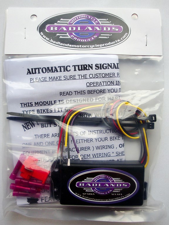
Badlands Automatic Turn Signal Shut Off Module Iii For Custom Built Motorcycles

I Have A 04 Flhtcui Last Time Out My Left Rear Turn Signal Light Started Staying On Here Are

Buy 2

Iq

In Desperate Need Of Wiring Diagram For 02 Zx-6r - Kawiforums

Adding Hazard Indicators

Suzuki U2013 Page 5 U2013 Circuit Wiring Diagrams

Running Led License Plate Lights Which Tail Light Wire To Tap Into - Kawiforums

Indicator Wiring Diagram Motorcycle
Diagram Buell Motorcycle Turn Signal Wiring Diagram
Download Buell Motorcycle Turn Signal Wiring Diagram
Your Nintendo Switch 2 console Nintendo Switch 2 AC adapter Power supply used for charging your device. (MOD. NGN 01), or other compatible AC adapter, and USB C cable Access to power outlet Remove your Nintendo Switch 2 from the dock when completing the following troubleshooting. What to do Unplug the AC adapter from both the wall and dock console.
Steps for when your Nintendo Switch 2 system won’t turn on, the screen stays black or off, or the system stays stuck in sleep mode.
Steps to initialize or format the Nintendo Switch system and delete all settings.
Follow these steps to change the menu color scheme on your Nintendo Switch 2 console.
How do you pair a controller to a Nintendo Switch 2 console? How many different controllers can be connected to a Nintendo Switch 2 console? How is the connection status indicated by the player LEDs on the controller? How is the order of the controllers indicated by the player LEDs? How do you disconnect reconnect a wireless controller from a console? How do you delete the pairing information ...
The information in this article can help you when: The wireless GameCube Controller for Nintendo Switch 2 will not power on. The player LEDs on the GameCube Controller will not light up or blink when pressing a button.
Additional information Use a licensed Nintendo Switch AC adapter for best performance results. Unlicensed products do not undergo Nintendo's testing and evaluation process and may have compatibility problems. Nintendo Switch systems do not have a power light.
How do you pair a controller to a Nintendo Switch console? How many different controllers can be connected to a Nintendo Switch console? How is the connection status indicated by the player LEDs on the controller? How is the order of the controllers indicated by the player LEDs? How do you disconnect reconnect a wireless controller from a console? How do you delete the pairing information on a ...
What to do An orange light indicates that the system is charging. This does not mean that the system will turn on immediately. It may take up to fifteen minutes of charging before the system turns on. It takes 3 ½ hours to fully charge the system (the time will increase if the system is being used while it is charging). Once charged, the system will remain charged for 3 5 hours if playing ...
If you are replacing a Nintendo Switch console with a Nintendo Switch 2 console, we recommend that you perform a system transfer to move your Nintendo Switch data to your Nintendo Switch 2. This will move your Nintendo Accounts, user profiles, save data, and Nintendo eShop purchases to the replacement console.
3 way switch,3 way switch wiring,3 way switch wiring diagram pdf,3 way wiring diagram,3way switch wiring diagram,4 prong dryer outlet wiring diagram,4 prong trailer wiring diagram,6 way trailer wiring diagram,7 pin trailer wiring diagram with brakes,7 pin wiring diagram,alternator wiring diagram,amp wiring diagram,automotive lighting,cable harness,chevrolet,diagram,dodge,doorbell wiring diagram,ecobee wiring diagram,electric motor,electrical connector,electrical wiring,electrical wiring diagram,ford,fuse,honeywell thermostat wiring diagram,ignition system,kenwood car stereo wiring diagram,light switch wiring diagram,lighting,motor wiring diagram,nest doorbell wiring diagram,nest hello wiring diagram,nest labs,nest thermostat,nest thermostat wiring diagram,phone connector,pin,pioneer wiring diagram,plug wiring diagram,pump,radio,radio wiring diagram,relay,relay wiring diagram,resistor,rj45 wiring diagram,schematic,semi-trailer truck,sensor,seven pin trailer wiring diagram,speaker wiring diagram,starter wiring diagram,stereo wiring diagram,stereophonic sound,strat wiring diagram,switch,switch wiring diagram,telecaster wiring diagram,thermostat wiring,thermostat wiring diagram,trailer brake controller,trailer plug wiring diagram,trailer wiring diagram,user guide,wire,wire diagram,wiring diagram,wiring diagram 3 way switch,wiring harness
